Hi, Can I use a 2 mb donor pcb with battery for a game without saving option?. For example: I want make probotector repro in a NHL 94 pcb, with a 27c160 eprom, it's possible?. must be wired anything?.
thanks.


Hi, Can I use a 2 mb donor pcb with battery for a game without saving option?. For example: I want make probotector repro in a NHL 94 pcb, with a 27c160 eprom, it's possible?. must be wired anything?.
thanks.
 Super Moderator

Yes you can. The SRAM will never be addressed so you can either leave it in or take it out. The battery can be removed too.Originally Posted by eterno002

Thank you, very much for your help ,Jazzmarazz.
Hi, I soldered eprom in the pcb and I only obtain screen with sega enterprises message and them black screen.
I checked the soldering and continuity is all right.I remove battery also, Can anyone help me?.
I attach a picture of my pcb.
IMG985.jpg
Last edited by eterno002; 26th-November-2015 at 14:18.
alright so I got a good deal on many 27c322 eproms and want to only use those. the first board I found as my first test was an acclaim 670128 that can be changed into a 32Mb board. I switched the jumper to J1 but it's still not working. while searching online I found an image of this board being used for a 32Mb game from default and it seems like it has some kind of resistor instead of the pure metal jumper
20140531_005530_0863_pcb_front.jpg
I programmed the unpadded rom (as people have been saying its not needed) and it doesnt work. I desoldered the rom and read it and did a hex compare to the original rom and they were the same.
Super Moderator
1. That is not a resistor, it is a jumper. You can tell becusse of the single black stripe. You're probably thinking "that's odd" but it was quite common to use since pick-and-place machines could grab them and place them.
2. Did you "byte-swap" the rom image before programming it?
Nope. This is the first I have heard of doing this. I do this with my SNES repros but I don't know how to do it with genesis. can you help me please?
Never mind. I went back and reread your stop about the software and read about how to byte-swap there! works perfectly now!. I skipped that step beffore because we have different programmers so I thought it was going to be specific to your programmer. dumb me. thanks for the great guide!
Last edited by Lotaphi; 24th-December-2015 at 04:16.
Super Moderator
Great work! What programmer do you have? I just got a new gq-4x for all of my repro needs. My tutorials may be based on that from now on.
 Member
Is there some sort of newbie's guide to what is needed to start doing your own repo's and DIY flash carts)? I am slowly getting out of console modding (TSOP Xbox's, GameCube XenoGC's, Dreamcast HDD mods, etc), and want to get into doing my own repo's and DIY flash carts.
That's what I have and it worked great. one of the burns I did though didn't burn the chip correctly for some reason. it was my 2nd eprom I tried where I padded the rom thinking that was the problem. it had a bunch of FF randomly in the wrong places when I hex compared it. other then that one time they have worked well.
Super Moderator
What kind of power supply are you using for writing eproms?
none, havent needed it yet as far as I know. I was going to attempt an atari repro once but it said I needed a power supply when i picked the chip for that. other then that it hasnt said I needed one for any of the chips I burn
Super Moderator
Seriously? Just USB power for a 27c322? That is great. The uv-eproms need high voltage for their vpp pin. That's great that usb power can handle these chips.
yep, so far the only ones that it said it needs power for are actually the older smaller chips for atari 2600 sized games. Though I haven't researched wether or not using power for things that don't need it adds any benefits such as faster burning or more stability.
Jazzmarazz, I have a question. I have a bunch of genesis boards with batteries on them and a lot of 27c322 eproms. how do I get this to work right? it didn't seem to work as easily as getting a non sram game working. most of the boards with batteries are all different too. Is there some universal way to get 27c322 to work on any of them to make games that need save functions?
Edit: So this was once again an issue with my not remembering/fully reading things again and it was because I didn't wire A20 (pin 32) of the 27C322 to pin 5 of the 74H00 IC. Now I need to see if I can get it to save (which I haven't tested yet, but it works now)
Edit 2: After testing it a few times it doesn't seem like it's saving correctly. I think the battery is working as it reads 3v using my multimeter so I'm not sure at this point what to do as I can't find any info on save issues using 27c322
Last edited by Lotaphi; 28th-December-2015 at 09:55. Reason: merged posts
Super Moderator
Looking back on my tutorial, that may be the problem. My statement is ambiguous as to whether the eeprom connects to pin 5 of the logic or if the cart edge connects to the logic.
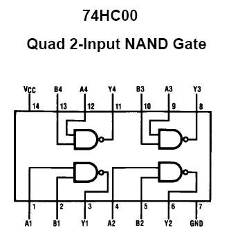
Pin 5 of the 74xx00 is an input, not an output. So what we are doing here is connecting two inputs together - nothing happens.
The 74xx00 is being used as a simple logic-based memory mapper comprised of only NAND gates (not and). The locations within the memory map for each IC can be determined with some logic equations. For example (not literally, but probably close):
IC_ROM = ~(CE*A20)
IC_RAM = ~CE*A20
So (still not being literal) when CE is low and A20 is low, ROM is enabled. When CE is low and A20 is high, RAM is enabled (ROM is disabled). That being said, we should be using A21 and not A20 if you want 2MBytes of ROM. A20 on the cart edge is actually A21 and 2^21 equals 2Mbytes which is split in half for each IC. The first 1Mbyte is allocated to ROM and the second 1MByte is allocated to RAM. I realize this is a bit much and difficult to explain.
What I mean to say is that I should edit my tutorial and be more clear. no one has questioned it before, so I guess it stayed incorrect for a long time. hehe
So.....
To clear everything up, first, what game are you trying to burn? How big is it? Does it only fill half of the 27c322? If the game is only 1Mbyte, we can connect pin A20 of your eeprom to ground and solve the issue. I think.
If your game is actually 2Mbytes, we will have to work a little harder.
 Posting Permissions